Παρασκευή 28 Σεπτεμβρίου 2012

Πως ενώνω δύο .avi αρχεία σε ένα; (merge 2 video files)


Αν έχουμε στην κατοχή μας δύο αρχεία .avi, για παράδειγμα μια ταινία που είναι χωρισμένη ώστε να χωράει σε δύο cds, μπορούμε πολύ εύκολα να την ενώσουμε σε ένα ενιαίο αρχείο χρησιμοποιόντας το δωρεάν πρόγραμμα επεξεργασίας εικόνας VirtualDub.
1. Ξεκινάμε κατεβάζοντας το VirtualDub. Δεν χρειάζεται εγκατάσταση (απλή αποσυμπίεση). Για να μπορέσουμε να κάνουμε και την πιό απλή επεξεργασία video, θα πρέπει να έχουμε περάσει στο pc μας κάποια codecs. Θα βρείτε δύο πλήρη πακέτα στα downloads (CCCP και KLite). Εγκαταστήστε μόνο ένα από τα δύο!
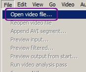
2. Ανοίγουμε το VirtualDub, και επιλέγουμε File > Open Video File:
ένωση αρχείων avi 1
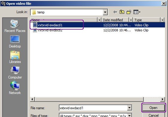
3. Επιλέγουμε το πρώτο κομμάτι της ταινίας, και πατάμε Open:
ένωση αρχείων avi 2
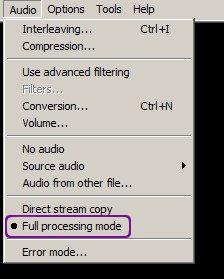
4. Πηγαίνουμε Audio, και επιλέγουμε Full processing Mode:
ένωση αρχείων avi 3
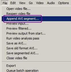
5. Πατάμε File > Append AVI segment, και επιλέγουμε το δεύτερο κομμάτι (όπως στο βήμα 3):
ένωση αρχείων avi 4
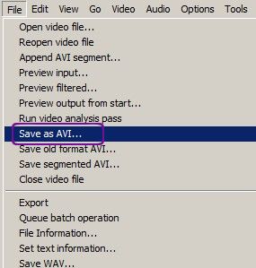
6. Τέλος πατάμε Save As AVI:
ένωση αρχείων avi 5
7. Επιλέγουμε το επιθυμιτό όνομα του καινούριου αρχείου, πατάμε Save, και περιμένουμε να ολοκληρωθεί η διαδικασία:
ένωση αρχείων avi 6

Read more...

Recover from a corrupted registry that prevents Windows XP

Recover from a corrupted registry that prevents Windows XP from starting by britec.co.uk

When you try to start or restart your Windows XP-based computer, you may receive one of the following error messages:

Windows XP could not start because the following file is missing or corrupt: \WINDOWS\SYSTEM32\CONFIG\SYSTEM

Windows XP could not start because the following file is missing or corrupt: \WINDOWS\SYSTEM32\CONFIG\SOFTWARE

Stop: c0000218 {Registry File Failure} The registry cannot load the hive (file): \SystemRoot\System32\Config\SOFTWARE or its log or alternate
System error: Lsass.exe

What your need is UBCD4WIN you can get that program here
http://www.ubcd4win.com/downloads.htm

Your also need files from System Volume Information folder, if you don't have any files in System Volume Information folder, you can use files from the repair folder.

Read more...

Σάββατο 22 Σεπτεμβρίου 2012

8 Great Emulators To Play Modern Home Consoles On Your PC (1994-2001)

home consoles of the 70s, early 80s and the transition from 16 bit to 32 bit in the early 90s. Just don’t go downloading any games (ROMs) you don’t legally own, OK?
As the systems get more advanced, emulation becomes more demanding and you may need a fairly recent PC, preferably a dual-core processor and a dedicated graphics card to get the most out of these.

1994 ““ Sega Saturn [Yabause]

home console emulators
Successor to the Mega Drive and loaded with two 32 bit CPUs, the Sega Saturn proved difficult for developers and early adopters alike. Due to the dual-processor architecture (a move some attributed to Sony’s looming powerhouse, the PlayStation) optimizing and building games for the platform required a lot of skill with Sega providing developers limited tools for the job.
The Saturn did sell well in Japan, but a lack of titles and the promise of Sony and Nintendo’s upcoming consoles meant PAL and North American models were discontinued in 1998 with Japan ceasing production two years later.
Yabause is a Sega Saturn emulator designed to run both .ISO CD images and commercial games themselves on a PC. The compatibility list is pretty good, and

1994 ““ Sony PlayStation [PCSX-Reloaded]
game console emulators
The Sony PlayStation took the world by storm and make a substantial dent on Sega and Nintendo’s market share. Over 100 million PlayStation consoles were sold in total before the latest revision of the machine was discontinued in 2006.
game console emulators
Nintendo certainly had a hand in Sony’s success, as they had planned on using CD technology manufactured by Sony in a joint venture as early as 1986. When Nintendo pulled out, Sony took a step back to see what they had come up with. They soon decided to direct their efforts towards a new age of hardware and video gamers, and the PlayStation was born.
You can emulate the PlayStation on Windows, Linux and Mac with one of the last remaining active PlayStation emulators, PCSX-Reloaded.

1996 ““ Nintendo 64 [mupen64plus]

gaming console emulators
After the immense success of the 32 bit Super Nintendo Entertainment System, the Nintendo 64 had a lot to live up to. Unfortunately for Nintendo the console didn’t sell as well as Sony’s PlayStation, though it did enjoy limited success shifting around 30 million units worldwide.
video game console emulators
The N64 was Nintendo’s last home console to use cartridge-based media, and due to the expensive manufacturing process games were expensive. Still, the system was home to some fantastic titles, including Mario’s first proper 3D adventure.
The cross-platform mupen64plus emulator works on Windows, Linux and Mac with decent compatibility for most N64 ROMs.

1998 ““ Sega Dreamcast [nullDC][lxdream]

video game console emulators
Sega’s last-ditch attempt at a home console came in the form of the 128 bit Dreamcast in 1998. It was the first console to feature online play via its bundled 56k modem. Despite never selling as well as Sega might have hoped, the Dreamcast will go down in history as a cult console for its cutting edge features and roster of genre-defining games.
video game console emulators
Dreamcast originals like Shenmue (which might never see an end to the series), Jet Set Radio (which featured early cel-shading) and Chu Chu Rocket (the world’s first Internet play console game) have elevated the console to cult status. Some independent companies are still releasing Dreamcast titles today.
If you’re a Windows user then nullDC should suffice for all your Dreamcast needs, whilst Linux and Mac users will want to try lxdream. Both emulators are still under active development, so don’t expect every game to work. As the Dreamcast is a fairly powerful device (not by today’s standards, but in terms of emulation) you’ll need a PC with plenty of power for best results.

2000 ““ Sony PlayStation 2 [PCSX2]

The PlayStation 2 is the best-selling console of all time, shifting 150 million units so far. The console has been such a success that Sony is still manufacturing the PS2 slim model, and the system has accrued nearly 11,000 titles.
The PlayStation 2 supported network gaming (which you can still enjoy on your original console with X-Link Kai), web browsing and some of the finest exclusive originals and arcade conversions of the generation.
Windows and Linux users can use PCSX2 to emulate the system, which can successfully launch and play a large amount of games. An issue with PS2 emulation is virtualizing the multiple cores within its processor, so the more power you’ve got under the hood the better. For best results you’ll need a Core2Duo or Core-i series processor 1GB of RAM and that all-important dedicated graphics card.

2001 ““ Nintendo GameCube [Dolphin]

The GameCube was Nintendo’s first console to use optical media, in the form of mini DVDs which could store up to 1.5GB of data. It featured a chunky controller with 2 analogue sticks, a d-pad and 8 buttons. The GameCube only sold just over 20 million units worldwide, and was not a great success for Nintendo.
The ground Nintendo lost with their last console (the N64) was even harder to make-up against new competition from Sony and Microsoft. The GameCube also only had four Internet-enabled games and a handful of system link titles.
This doesn’t mean there weren’t some excellent games released for the system! The fantastic Dolphin emulator plays both GameCube and Wii games on Windows, Linux or Mac (Intel OS X). What’s even more amazing is that this emulator upscales Wii and GameCube titles to high definition, a feature that’s not possible on original hardware. What are you waiting for?

2001 ““ Microsoft Xbox [DxBx]

What happens when the world’s largest software corporation enters the games console market? A big, black, powerful, online-geared behemoth is what ““ the Microsoft Xbox. Despite the lure of top-selling Halo: Combat Evolved (and its even more successful sequel) the Xbox only sold marginally better than the GameCube, shifting around 25 million units before discontinuation in 2006.
home console emulators
DxBx is an Xbox emulator written in Delphi. Whilst playable game support is thin on the ground, it may interest some die-hard Xbox fans. Only a handful of games run at the moment but if you’re interested in Xbox emulation development you might want to check it out.
If you really are desperate for an Xbox you can get them cheap on eBay, or play some Xbox classics on the Xbox 360.

Read more...

Specifications for Cat3, Cat4, Cat5, Cat5e, Cat6, and Cat7 Cables


Ethernet Cables
Comparison between CAT5, CAT5e, CAT6, CAT7 Cables
Quote Requests                              Buy Online
In the context of the 100-ohm UTP (Unshielded Twisted Pair) type of cable used for Ethernet wiring the only categories of interest are Cat3, Cat4, Cat5, Cat5e, Cat6, and Cat7. CATx is an abbreviation for the category number that defines the performance of building telecommunications cabling as outlined by the Electronic Industries Association (EIA) standards. Some specifications for these categories are shown further down.
Up until the late 1980s thick or thin coaxial cable was typically used for 10-Mbps Ethernet networks, but around that time, UTP cabling became more commonly used because it was easier to install and less expensive. UTP CAT3 and CAT4 were used for a quite limited time since the emergence of 100Base-TX networks meant a quick shift to CAT5. By the year 2000, moves to gigabit (1000Base-TX) Ethernet LANs created a need for another specification, CAT5e. CAT5e is now being superseded by CAT6 cable and there is a developing standard for CAT7.
Specifications for Cat3, Cat4, Cat5, Cat5e, Cat6, and Cat7 Cables
Category Type Spectral B/W Length LAN Applications Notes
Cat3 UTP 16 MHz 100m 10Base-T, 4Mbps Now mainly for telephone cables
Cat4 UTP 20 MHz 100m 16Mbps Rarely seen
Cat5 UTP 100MHz 100m 100Base-Tx,ATM,CDDI Common for current LANs
Cat5e UTP 100MHz 100m 1000Base-T Common for current LANs
Cat6 UTP 250MHz 100m   Emerging
Cat7 ScTP 600MHz 100m    
It might seem that CAT5 and CAT5e are the same. Pretty much they are, the CAT5e specification simply included some additional limits over the CAT5 specification. The reality is that most CAT5 cable is in fact CAT5e cable just not certified as such. Here is a comparison of those extra specifications.
CAT5, CAT5e, and CAT6 UTP Solid Cable Specifications Comparison
  Category 5 Category 5e Category 6
Frequency 100 MHz 100 MHz 250 MHz
Attenuation (Min. at 100 MHz) 22 dB 22 dB 19.8 dB
Characteristic Impedance 100 ohms ± 15% 100 ohms ± 15% 100 ohms ± 15%
NEXT (Min. at 100 MHz) 32.3 dB 35.3 dB 44.3 dB
PS-NEXT (Min. at 100 MHz) no specification 32.3 dB 42.3 dB
ELFEXT (Min. at 100 MHz) no specification 23.8 dB 27.8 dB
PS-ELFEXT (Min. at 100 MHz) no specification 20.8 dB 24.8 dB
Return Loss (Min. at 100 MHz) 16.0 dB 20.1 dB 20.1 dB
Delay Skew (Max. per 100 m) no specification 45 ns 45 ns
If you're cabling a mission critical system or you want your network to be future proof, go for the CAT6 cables (and patch panels and connectors), but for the average home or small office network CAT5 or CAT5e will be just fine.
Crossover Cables vs Straight Through Cables Ethernet patch cables can be wired in three different ways, the two main ways are called straight through and crossover. The third type is called rolled and has only specialized applications.
Generally speaking, straight through cables are used to patch between different types of equipment; for example, PCs to a hub.
Conversely,
crossover cables are generally used to patch between similar types of equipment; a PC to another PC for example.
Some modern hubs don't care if you use crossover cables or straight through cables, they work out what you're using and configure themselves accordingly.

As stated at the outset, the actual difference is in the wiring. Inside the UTP patch cable there are 8 physical wires although the network only uses 4 of them (the other 4 are simply wasted). The 8 wires are arranged in what's known as pairs and one pair is used to send information whilst the other pair is used to receive information.
On a PC, the pair on pins 1 and 2 of the connector send information, whilst the pair on pins 3 and 6 receive the information. To make PCs talk to each we therefore need to connect the send pair of one PC to the receive pair of the other PC (and vice-a-versa). That means we need a crossover cable. If we used a straight through cable the both be listening on the one pair - and hearing nothing, and sending on the one pair - achieving nothing.
Electrically, the straight through and crossover cables look like the diagram below: The most common cable is the straight through cable. In a home or small office network you might only have one crossover cable used - perhaps from the cable or DSL modem to the distribution hub. How do you tell what sort of cable you have in your hand? You can tell by looking at the connectors, identifying the wiring from its colors, and comparing the ends. See the next question on color codes.
Color Codes
The standards say that Ethernet connectors should be cabled with specific colors on specific pins. There are two standard layouts - if a cable has the same layout on both ends it's a straight through cable. If a cable has one layout on one end and the other layout on the other end then it's a crossover cable. Whilst not universal, the color codes shown below are generally used on professional cables.
If a cable has 568A color wiring on both ends then it's a straight through cable.
If a cable has 568B color wiring on both ends then it's also a straight through cable.
If a cable has 568A color wiring on one end and 568B color coded wiring on the other end, then it's a crossover cable.
In fact, while the colors are standardized and usually followed, that's not the important part. What's more important is that one "pair" (wires that are twisted together inside the cable sheath) is used for the transmit side and another pair for the receive side. If pairs aren't used then it's likely your cable will not work. Pairs are identified by the colors. The orange wire and the orange with white stripe (or sometimes white with orange stripe) wire are a pair. The brown wire and the brown with white stripe wire are a pair. Etc.
Network Cables vs Patch CablesA short lead with connectors on either end which is flexible and is used to plug one piece of equipment directly into another is generally referred to as a patch cable. To make them flexible, patch leads are generally made with stranded wire.
Cables with solid core wires are more often used in permanent wiring and terminate on wall sockets and may be sometimes referred to as
network cables. These cables aren't so flexible (and will break is repeatedly flexed).
Solid Core Cables vs Stranded Cables Solid conductor uses 1 solid wire per conductor, so in a 4 pair (8 conductor) roll, there would be a total of 8 solid wires. Stranded conductor uses multiple wires wrapped around each other in each conductor, so in a 4 pair (8 conductor) 7 strand roll, there would be a total of 56 wires.
Read more...

Κυριακή 16 Σεπτεμβρίου 2012

The Secret History Of Hacking

Read more...

Linux - Best native games

Read more...

Microsoft Office vs OpenOffice / LibreOffic

Read more...

How to build a Home Network


Part I. Introduction


You are encouraged to make links to this article from your website and tell your friends

The following article is based on years of experience. It is provided as a free service to our customers and visitors. However, Directron.com is not responsible for any damage as a result of following any of this advice.

Copying the contents for commercial purposes is strictly prohibited without Directron.com's written consent. However, you are welcome to distribute these computer support tips free to your friends and associates as long as it's not for commercial purposes and you acknowledge the source. You are permitted and encouraged to create links to this page from your own web site.


How to build a Home Network? By Jerry Saeva

Less than 20 years ago, most people did not have a personal computer. Today, many households have more than one computer. This, combined with the growing popularity of broadband Internet access, has created an increased interest in home networking. Connecting all your computers together on a home network not only allows you to share the same Internet connection, but other resources such as printers, storage devices and files. Home networks are also popular with game enthusiasts, allowing multiple gamers to compete over the home network.

This manual is a description of how to setup and configure a home network that shares a broadband Internet connection. It will cover everything from running network cable and choosing the hardware to setting the network parameters on your computer. After reading this, you should be able to quickly setup your own network and begin sharing the Internet.

Part II. Choosing a Network Setup


There are several ways you can setup your home network. While some options may be cheaper than others, they are typically much less flexible when it comes time to expand your network. This manual will focus on network setups using a broadband Internet connection. If you have a dialup connection or no Internet access at all, you should still be able to adapt the information in this manual to suit your particular configuration.

Network Hardware: a brief explanation
To help understand the differences between the network configurations explained in this section, you should first know and understand the hardware used in them.

  • Ethernet/10BaseT: Ethernet is the type of network technology used by almost all home networking hardware available today. Ethernet is a "baseband" technology, which means that all the bandwidth of the cable used in the network is utilized in one single channel. Since there is only one channel, all computers "hear" all the traffic from other computers and filter the information based on addresses. 10BaseT is a specific type of Ethernet that uses Category 5 cable and RJ45 connectors. The 10 represents the maximum throughput (10 Mbits) and Base T refers to the baseband technology used in Ethernet. Note that 100BaseT is the same thing with the exception of the maximum throughput of 100 Mbits.
  • Network Interface Card (NIC): a PC card that connects the PC to the network. This connection is either to another PC's NIC, a hub or a router. NICs are available for ISA or PCI bus slots, although PCI is recommended if you have a PCI slot available. NOTE: in all the diagrams shown below, a line connected to a PC or laptop indicates a connection to a NIC. The computer labeled "Main PC" requires a NIC for each line connected to it. Also, this manual assumes the use of an Ethernet NIC using RJ45 connectors (10BaseT/100BaseT).
  • Hub: A device that allows you to connect two or more computers together such that all computers can communicate to all others. A hub (or a router with a built in hub) is required if you want more than two computers in the network. Without it, you would need a NIC for every computer connection (i.e., if PC A is connected to PC B and C, it would need two NICs, one for B and one for C, each using a cross-over cable).
  • Router: Generally, a router does just that; routes network traffic to specific sections of a network (called sub-nets), which reduces unnecessary traffic in subnets. Most routers (including Cable/DSL routers) come with a built in hub (i.e., have multiple ports), however, there are some that will require an additional hub.
  • Cable/DSL routers: Specialized routers that allow the sharing of a single cable/DSL Internet connection. Unless you pay for additional IP addresses, most cable/DSL Internet connections supply only a single address. The router supports sharing this single address using Network Address Translation (NAT). This protocol translates between the single cable/DSL address and all other addresses on the home network, thus requiring only one address outside the home network. NOTE: in the configurations that do not use a cable/DSL router, the "Main PC" performs the NAT using "Internet Connection Sharing" built into Windows 98 SE and Higher.

Two computer network with no hub
If you have only two computers and will not want to add any computers to the network in the future, you can use this simple setup. There are two drawbacks to this configuration: 1) you cannot add additional computers to the network and 2) the cable between the client PC and the main PC must be made as a "cross-over". The advantage of this configuration is that a network hub is not necessary

In this configuration, the main PC is connected to the cable/DSL modem and shares the Internet with the client PC. We will see later how the main PC acts like a router to allow simultaneous access to the Internet for both the main PC and client PC. Also note that this configuration requires that the main PC have TWO NICs, one connected to the cable modem and one connected to the client PC.


Computer Network Using a Hub
In this configuration, all the computers in the network are connected to a central network hub, while the main PC is also connected to the cable/DSL modem. The cables used to connect all the computers to the hub are standard "patch cables" (will be discussed later in the network cabling section). A hub is required for this configuration, but allows for multiple "client" computers to be networked with the main computer.

The number of computers that can be added to the network is limited to the number of ports on the hub. There are many different hubs available with varying number of ports. Most hubs have an "uplink" port that allows daisy-chaining hubs together to expand the total number of ports on the network. The good news is that hubs are relatively cheap (under $25) so this does not become a large cost factor in your overall network.
Similar to the previous Two computer network configuration, the main PC acts like the router and must have two NICs, one for the cable/DSL modem and the other connected to the hub. Any Internet access to the client PCs must be "channeled" through the main PC. The next configuration, while it is a bit more expensive, eliminates the need for the main PC to act as the router


Computer Network Using a Cable/DSL Router A more expensive, but more flexible network configuration is one that uses a cable/DSL router. The cable/DSL router allows you to connect multiple computers directly to the cable/DSL modem without having to go through a "main PC" Note that a cable/DSL router is about 4 times the cost of a hub, but is worth the additional cost.

The other benefit of a cable/DLS router is that it acts as a hardware-based firewall to protect your home network from outside "hackers" To get this same firewall benefit in the other two configurations, you would have to install a software-based firewall application. For more general information on firewalls, visit the Home PC Firewall Guide.

Other Variations
  • Phone-line networks: This type of network uses existing phone lines in your home to connect the computers together instead of running additional network cables. The max throughput is typically 10Mbit (verses 100Mbit using an Ethernet based cabling system). Also note that different vendor's phone-line network cards (NIC) may not work together properly.

  • Wireless: Possibly one of the most expensive options for a home network, the use of wireless hardware gives you complete flexibility as to the locations of the PCs on the network. You won't have to run any cable at all. Most wireless receivers also are routers, giving you cable/DSL sharing along with wireless client PC locations.


Part III. Network Cabling


Now that you have chosen a network configuration and generally know where your computers and cable/DSL modem will be located, you can run the network cables. This section describes what cable to use and how to add connectors to the cables. NOTE: if you are using a phone line or wireless configuration, you can skip this section.

What type of cable to use?
To connect your computers to the network (i.e., another computer, a hub or a router), you need to use the correct type of cable with the proper connectors. The most common network cable used today, that will support up to 100 Mbit connections, is 8-wire "category 5" cable. This cable is abundantly available in electronics stores, computers stores, home improvement stores and even on-line.

As with any type of wire, the price per foot decreases as you purchase more. For example, here at Directron, 100' is $29 (29 cents/foot) while 1000' is $59 (5.9 cents/foot). It is most advantageous to buy all your cable at once and in bulk to get the best price.

Some cable can be purchased with connectors at both ends, while "bulk" cable does not contain any connectors. Having the connectors on the cable is convenient because you do not have to put them on yourself, but they can become a problem (possibly breaking off) when you are running the cable through walls or in your cellar or attic. Furthermore, it will be more difficult to get a volume discount price. The recommendation is to buy all your cable in bulk and apply the connectors yourself. Of course, your situation may vary and it may be more economical to by the cable with connectors. This manual will discuss how to put on the proper connectors.

How Much cable do you need?

Ironically, the best time to run network cable in your house is when you are building it. Before the wallboard is applied you have great flexibility as to how the cable is run, using the minimum amount necessary to get between rooms. If you are building a home, it is strongly recommended to get a large bulk amount of cable (e.g., 1000 foot bulk box) and run a line from every room in the house (probably skipping the bathrooms) to a central location. In this central location, you can connect any or all the rooms to the router or hub giving your whole house network access. You can even tell your friends you have a "network closet" in your house!

Assuming you do not have this "luxury" you have to estimate your cable length based on which rooms in the house require network access. There really isn’t any good "formula" to use, but keep these things in mind when you are estimating:

  • Are you going up more than one level of your home? Remember to add the distance "up" as well as "across" the house.


  • When you have to run the wire in your cellar or attic, remember that you may have to move around existing obstacles (plumbing, heating/cooling ducts, etc.), so don’t expect you can go in a perfect line.
Note: the maximum length that any one of your cables can be is 100 meters.

Adding connectors

Almost all modern NICs, hubs and routers use a type of connector called "RJ45" This is an 8-pin plastic connector that looks like a large version of a telephone connector. To put these connectors on the cable, you will have purchase or borrow an RJ45 crimping tool. The tool is necessary because it not only clamps the connector onto the cable, but also pushes the teeth of the connector into the individual wires of the cable. Do NOT attempt to apply these connectors without the proper crimping tool.


Although the task of installing the connectors on the cable looks complicated, it is quite simple. Here are the steps to install and crimp the connector.

Step 1: Stripping the cable. The crimping tool has cable stripping blades and a "stop" on one side. Insert the cable so the end hits the stop and gently close the clamp to cut the outer insulation. Gently pull the cable from the crimper. Warning: if you apply too much pressure when closing the blades together, you may cut into one of the individual wires. If this happens, cut the stripped part of the cable off and try again.


Step 2: Choosing the correct Pin-out. Most cat-5 cable contains 4 sets of "twisted pairs" of wires. Each pair is a combination of a solid color and a "striped" color (white with a stripe the same color as the solid wire). The colors are orange/orange-white, green/green-white, blue/blue-white and brown/brown-white. The "pin-out" refers to the order of these wires at both ends of the cable. This order depends on which type of cable you are attempting to create, either "straight-through" (for computer-to-hub connection) or "cross-over" (for computer-to-computer connection).


When creating a "straight-through" cable, the order of the wires must be the same on both ends of the cable. Although the colors used in each position is not truly critical, the standard order used is like the picture to the left (note that the clip of the RJ45 connector is on the bottom):

If you need to make a crossover cable (when connecting a computer to another computer without a hub), then one of the ends of the cable should use the wire order to the left and the other end must use the wire order shown in the picture to the right (the color scheme here MUST be used).


Step 3: Inserting the cable into the connector. Once you have moved the individual wires so they are in the correct order (matching the proper pin-out chosen in the previous step), carefully insert the cable into the RJ45 connector. The individual wires should slide into grooves inside the connector. Since the connector is clear, you should be able to confirm the wires are still in the same order. It should look like the picture below.


Step 4: Crimping the connector. : Insert the RJ45 connector into the crimping tool with the connector’s clip fitting into the guide built into the crimper. The gold teeth of the connector should be facing the teeth on the crimper. Make sure the connector is pushed all the way into the crimper until it cannot go any farther. This ensures the teeth of the crimper are properly aligned with the teeth of the connector. Close the handles of the crimper firmly together. Test the connection by gently tugging on the cable to ensure it does not come out of the connector.


Using other types of jacks If you want your cable to terminate into a wall jack or flush mount receptacle, there are many jacks and receptacles available to help make your home network look more "professional" For example, you may have a laptop with its own network card/cable that terminates with its own RJ45 connector. In this case, it is easier to place an RJ45 jack on the wall instead of terminating the cable with an RJ45 and using a "coupler"

There are two items of interest. One is a single wall jack that is self-contained in its own small case. The case can be screwed to the wall or secured with double-sided tape. See photo for an example of this. Another option is the use of "keystone" jacks and wall plates. If you have an existing outlet box or are running wire prior to the wallboard being installed, you can use this system. This system allows you to put multiple jacks in the same outlet box.

Both of these types of jacks come with a set of slots where the each wire of the cable is placed, then a clip (or sometimes two clips) are placed over the wires and when pressed in, forces the wires into clips that also cut into the insulation to make the contact. This eliminates the need to strip each individual wire.

Part IV: Installing and Configuring the Hardware


Now that you have the cables placed in the appropriate room(s), you need to install some hardware into the computers that will be on the network. In addition, if you are using a hub or router, this must be "installed" and/or configured. Note: some newer computers are coming with network cards installed in them (or integrated on the motherboard). Make sure to check for this before purchasing a NIC for that computer. Also note that, although this manual has mentioned some other types of network interfaces besides Ethernet, this section focuses only on the use of Ethernet-based hardware.

Installing the Network Interface Cards (NIC)

Each computer on the network must contain a NIC, with one exception: if you are going to use a network setup (chosen earlier in this manual) that will utilize “Internet Connection Sharing? one of your computers (the one connected to your cable or DSL modem) will require TWO cards. This paragraph discusses installing an NIC into a desktop computer. If one of your computers is a laptop, the process is similar, except that you will have to purchase a PCMCIA NIC instead of an ISA or PCI card.

Here are the steps to install a NIC into your computer…repeat this process for each computer in the network.

Step 1: Choosing the NIC with the right bus type. The most common type of bus slot available on your motherboard will be a PCI slot. PCI slots are rather short and are almost always white. The other type of slot that is still common on many computer motherboards is the ISA slot. ISA slots are longer than PCI slots and are black. You will need to determine which type of slot is available in your computer before you purchase the NIC to make sure you get the right type. If you have a choice, get a PCI type NIC.


Step 2: Read the NIC manual. This may sound like a silly step (and typically a step skipped by most people), but some manufacturers have integrated installation programs for the drivers of their cards, requiring you to install the driver first, while others require you to install the NIC first, especially if the card states it is "plug-and-play" If the manual directs you to install the driver before the NIC, then do so now by running the installation program referred to by the instruction manual.

Step 3: Insert the NIC into the computer. Shut down the computer and turn it off. Open the case and find the available slot on the motherboard. Remove the cover plate on the back of your computer’s case for the slot that you chose. Insert the card into the slot and press it in firmly. Screw the card to the case and replace the case’s cover.

Step 4: Load the driver. Power on the computer. If you have already run an installation program, then follow the instructions (if any) that are shown when the operating system boots. If you have not already run an installation program, then the card should be auto-detected by Windows and Windows will ask you for the driver for the new hardware. Follow the instructions for the "new hardware wizard" and reboot the computer when prompted. The OS may prompt you for both the driver CD/Floppy and the Windows 98 CD.

NOTE: If you are installing two or more NICs in the same computer then you will need to repeat steps 1-4 for each card. (two NICs may be needed on one of the computers if you are using the Internet Connection Sharing feature in Windows)

We will later have to ensure that the proper network protocols and network client is installed and assigned to the NIC(s) in the computer. This will be discussed in the Configuring the network protocols and client section.

Setting up Cable/DSL router
One of the many benefits of using a Cable/DSL router instead of Internet Connection Sharing is the easy setup. Many routers require very little work to setup and may work by simply plugging them in and rebooting the computer and the cable/DSL modem. Since all routers have different configuration interfaces, this section will touch on the areas that you may have to change on your router to configure it properly, but keep in mind that you will have to read the owner’s manual of your router for more details.

Note: this section assumes that all the computers to be connected to the router have already been fitted with one NIC each. Refer to Installing the Network Interface Cards (NIC) for details on how to add the NIC card to the computer.

Step 1: Determine if your Cable/DSL modem uses DHCP or a fixed address. Before you begin setting up the router, you should know if your cable or DSL modem uses Dynamic Host Configuration Protocol (DHCP) to supply an address to your computer or if your Internet Service Provider (ISP) has given you a fixed network address. DHCP is a method in which the device attached to the modem (in this case, the router) asks the modem for the address to use when communicating on the Internet. Each time the router is restarted, the modem may supply the router with a different address. If your ISP does not support DHCP, then they would have given you a specific IP address when they setup your connection. An IP address will be a series of 4 numbers between 0 and 255, separated by periods, such as 192.168.10.123. If you are unsure, call your ISP. Almost all cable ISPs (such as RoadRunner) use DHCP.

Step 2: Connecting the power and network cables. Follow the directions for your router on how to connect power to the router. The only other connections you need to make are the network cables to the router. Note: most routers will have a separate labeled port for the connection to the modem, most commonly called "WAN" (see photo). Connect the other end of the network cables to the appropriate device (PC or Cable/DSL modem).


Step 3: Configuring the router for DHCP or fixed address. All routers will have their own unique configuration user interface. A common aspect of these interfaces is that many of them are available using a web browser. If your router doesn’t have a browser interface, you will have to install the setup/configuration software that came with the router. Again, you will have to read your manual.

Once you are familiar with the router’s configuration interface, go to the screen/page that allows you to enable or disable DHCP. Note that the router is not only a DHCP client to the modem, but also a DHCP server to all the PCs connected to it. You are looking to change the DHCP settings for the router to the modem (may be listed as “WAN configuration?.

When you have found the correct section of the configuration, either enable DHCP or disable it and enter the specific IP address that you received from your ISP. IMPORTANT: after you save your changes to the router configuration, you need to reset (power off/on) BOTH your router AND the modem.

Other configuration options of the Cable/DSL router

Depending on the make and model of your router, there may be many other features that can be configured to get the most from your router investment. This section will briefly describe some of the features that are available on some routers. You will have to refer to your router’s manual to see if it has any of these features and if so, how to use and configure them.

  1. Static IP Addressing: most all routers not only are DHCP servers, but can also be configured to support computers or other devices that may have static IP addresses. For example, you may have a network capable printer that has a static address and would like to make it available to other computers on the network. Your router should allow you to add static IP addresses that will be recognized and serviced by the router.
  2. Internet Access Control: Some routers give you the ability to disallow access to the outside Internet to specific computers connected to the router. This control can be on/off all the time or be set to be unavailable at specific times (such as during "working" hours). For home networks, this feature can become useful if you need to control access to the Internet to the younger members of the family.
  3. Support Personal Web Server: If you need to have a computer on your internal network visible to the outside Internet, the router may support this. This is useful only if you want to support a computer as a file or web server. Obvious care is needed if this feature is used because it bypasses some or all of the built-in firewall features of the router.
  4. Internet Access Monitoring: Less common on the less expensive routers is the ability to monitor and track the activity of computers on the Internet. This is a feature more often used by small businesses and less often in the home network environment.
By no means is this an exhaustive list. Some routers (like the Linksys BEFN2PS4) support additional features such as Internet long distance phone features. If you require special features beyond the simple sharing of the Internet connection, be sure to research the routers available before making your purchase.

Part V: Configuring the Software


Now that we have all the hardware installed and configured, we have to configure the computers and other software in the network. Note: a few items in the section (such as "Setup up Internet Connection Sharing") are needed only if you do not have a router and are going to use Internet Connection Sharing.

The paragraphs in this section outline the steps to setup the software using Windows 98. Where possible, indications of the differences between Windows 98 and Windows 2000 are mentioned.

Configuring the network client:

In earlier steps of this manual, we installed the NICs in the computers and added the appropriate drivers for those cards. We now have to make sure that the appropriate network client is installed. NOTE: This section applies to all computers on the network, including the one that will run the Internet Connection Sharing (if you are not using a router).

Step 1: Installing the Network Client. the installation of network cards and their drivers almost always ensures that a network client is also installed. To be sure one is installed, however, choose Start -> Settings -> Control Panel -> Network to open the network window. It should look like the picture below. At the top of the list box on the Configuration tab will be the installed client (if any). If you DO NOT see "Client for Microsoft Networks", do the following:

  • Click the Add button
  • On the "Select Network Component Type" dialog, select "Client", then click Add
  • On "Select Network Client" dialog, choose Microsoft as the Manufacturer (left side) and "Client for Microsoft Networking" as the client (right side). Click OK.


Step 2: Choosing the "Primary Windows Logon". In Windows 98 on the Network Window (see picture), there is a field labeled "Primary Network Logon". Click on this field and choose "Windows Login" The next time the computer is rebooted, you will be prompted for a password. If you leave the field blank and click OK, you will not have to supply passwords in the future.

Step 3: Setting the computer Identification. If you want to take advantage of sharing printers and files between computers in addition to sharing the Internet connection, all the computers on the network must have a computer name and use the same "Workgroup". To set this, do the following:

  1. If you are not already on the Network window, click Start -> Settings -> Control Panel, then double-click the network icon in the control panel window.
  2. Click the "Identification" tab (second from left) on the Network window (see picture).
  3. Enter a computer name (up to 15 characters) that is unique from all other computers on the network. This is the name you will use when connecting to this computer from others on the local network.
  4. Enter a computer workgroup name (up to 15 characters) that is the SAME as all the others on the network. Use the default "WORKGROUP" if you do not have a specific preference of the name.
  5. Optionally enter a description for this computer (up to 48 characters). This comment can be viewed by others on the network to help understand what each computer does (or where it is).
  6. Click OK to save the changes. You may be asked to reboot.


Noteworthy differences between Win98 and Win2K. The following is a small list of differences between the setup steps described earlier and what you have to do in Windows 2000:

  • To see and configure network client and ID, you have to click "Start -> Settings -> Network and Dial-up Connections". You will be presented with a window with an icon for every NIC in the computer as well as for every dialup connection you have on your computer. To get the equivalent of the "Network" window in Win98, you have to double-click the "Local Area Connection" icon that corresponds to the NIC you are trying to configure.
  • On the Local Area Connection (LAC) window, there is a set of check boxes for the client, service and protocols that can be assigned to the SPECIFIC network card, instead of showing all cards, all protocols, and so on as Win98 does.
  • On the Local Area Connection window, there is an Install and Uninstall button instead of Add and Remove.
  • To set the computer name and workgroup, go to your desktop and right-click on the "My Computer" icon, then choose "Properties" On the System Properties window, click the "Network Identification" tab, then click the "Properties" button (see picture).


Setting up Internet Connection Sharing

Earlier in this manual, you had chosen a network setup based on whether or not you were going to use a router. If you are using a router, SKIP THIS SECTION. If you are not using a router but you want to share your internet connection with other computers on the network, you have to install and configure a component of Windows 98 Second Edition (SE) and Windows 2K called "Internet Connection Sharing" (further referred to as ICS). This component is NOT available in Windows 95, Windows 98 first edition or Windows NT 4.0. To verify if you have the second edition of Windows 98, right-click on "My Computer" on your desktop and choose properties. The operating system listed at the top of the system properties window will state "Second Edition" (version 4.10.2222).

Installing/Enabling ICS on one computer. To install ICS on the computer connected to the cable or DSL modem, follow these steps:

  1. Click Start -> Settings -> Control panel. Double click on the "Add/Remove Programs" icon in Control Panel window.
  2. In the "Add/Remove Program Properties" window, click on the "Windows Setup" tab.
  3. Scroll the "Components" list until you find "Internet Tools". Click on the name of the row (not the check box), and then click the "Details" button (see picture).
  4. At the top of the Components list on the "Internet Tools" window, you will find the "Internet Connection Sharing" component. Click on its checkbox, and then click OK. Click OK or Apply on the "Add/Remove Programs" window.
  5. At this point, you may be asked to insert your Windows 98 SE CD. If prompted for this, insert the CD and click OK. After you do this (or if you are not prompted), the Internet Connection Sharing Wizard should be started. Click Next on the first wizard window.
  6. The second wizard window should be displayed. It lists all the network cards you have in the computer and asks you to choose the card that will be used for the Internet connection. Choose the card that is connected to your cable or DSL modem (see picture). Click Next.
  7. The next wizard window informs you that it will be creating a network configuration disk. Click Next. When prompted, insert a blank floppy disk into your computer and click OK. When it is finished creating the disk, remove the floppy and click OK.
  8. The wizard is now complete. Click Finish on the last wizard window. You will be asked to reboot. Click OK to reboot (the network will not function until you do).


ICS on Windows 2000. Enabling ICS on Windows 2000 requires a different set of steps (and a smaller one at that). First, note that you will not be able to enable ICS on Windows 2000 until there is at least two network cards (or one card and one dial-up connection) in the computer (which makes sense). Follow these steps:

  1. Click Start -> Settings -> Network and Dial-up Connections; the "Network and Dial-up Connections" window will be displayed.
  2. Right-click on the "Local Area Connection" icon that represents the network card connected to your cable or DSL modem and choose "Properties". If you do not know which one it is, try each until the name of the proper network card is shown at the top of the window.
  3. The window that is displayed should have a "Sharing" tab (see the picture below). Click on this tab. If the Sharing tab is not available, you do not have at least two NICs in the computer, or you do not have administrator rights on the computer.
  4. Click on the "Enable Internet Connection Sharing for this connection" box, and then click OK.
  5. You may see a warning about the other connection (network card) being assigned a static IP address; this is expected, since the computer supporting ICS must have a static address on the connection to the internal network it will service.


Setting up client computers

The rest of the computers on the network (referred to as the "client computers" have to be configured to access the Internet using the network card and to request the ICS computer or cable/DSL router for an automatic IP address. There are two ways of doing this:

Using disk created by installation of ICS. if you are using a computer running Internet Connection Sharing, you can use the configuration disk that was created when you installed ICS (see previous section). NOTE: this will work only on computers running Windows 95 or 98. Simply run the "icsclset.exe" file found on the floppy. Click next (or finish) on each of the three wizard windows.

Use the "Connection Wizard". If you are using a router or did not make the configuration disk when you installed ICS, you can set the configuration manually. Most installations of Windows 9x will place a "Connect to the Internet" icon on your desktop. Double-click to start the connection wizard. If this icon is not available on your desktop, do the following to start it:
  1. Click Start -> Settings -> Control Panel
  2. Double-click the Internet Options icon
  3. Select the "Connections" tab, then click the "Setup" button at the top of the tab
For the Internet connection wizard, do the following:
  1. Choose the "I want to set up my Internet connection manually?" option and click Next.
  2. Choose "I connect through a local area network (LAN)", and then click next.
  3. Click next again.
  4. Choose "No" to setting up a mail account and click next
  5. Click finish.
Wow! After all that work, you should now be completely up and running. If there are any problems, turn off ALL your hardware (computers, modems, routers, hubs, etc) and then turn them on in the following order:
  1. Cable or DSL Modem
  2. Router or hub
  3. Computer running ICS, if you have one
  4. All other "client" computers on the network.
Setting up file and printer sharing

Now that you have everything setup to share you Internet connection on your network, you may also want to take advantage of sharing other resources between computers, like printers or files There are two main parts to doing this: 1) adding the "file and print sharing" service to any computer that you want to allow other computers to share and 2) taking advantage of these shared resources on the other client computers.

Enabling file and print sharing. on all the computers where you want to share files or printers, you must first enable "file and print sharing services". To do this, follow these steps:

  1. Click Start -> Settings -> Control Panel
  2. Double-click the Network icon in the Control Panel window
  3. Click the "File and Print Sharing" button
  4. A dialog will appear with to options that you can select separately; one for sharing files and one for sharing printers. Select either or both based on your sharing needs.
  5. Click OK. If you did not already have it installed, the OS will automatically add the "File and print sharing for Microsoft Networks" service to the network components list on the Network window. Click OK on the Network window. You may need to reboot.


Selecting directories to share. after enabling file and print sharing, you have to choose the directories and/or drives that you want to "open" to the other computers on the internal network. You can share an entire drive (even a CD or ZIP drive) or a specific subdirectory path (and all directories beneath). Follow these steps to share files:
  1. Open the Windows Explorer (click Start -> Programs -> Windows Explorer).
  2. Traverse to the directory or drive that you want to share. Right-click on the drive or directory and choose "Sharing" from the menu. Note that if you want to share an entire drive, select the drive letter instead of a directory.
  3. Select "Shared As" option and enter a name in the "Share Name" field (or leave the default name).
  4. For "Access Type", you can choose one of the following three options:
    1. Read-Only: choose this if you want to get only read access to others on the network. They will not be able to modify or delete any files in that area. You can supply a password in the "Read-Only Password" field if you want to force users of other computers to supply a password before gaining access.
    2. Full: if you want other computers to have both read and write capabilities, choose this option. As with the "Read-Only" option, you can supply a password in the "Full Access Password" field.
    3. Depends on Password: choose this option if you want to give some users read-only and others read and write access. You will have to supply two separate passwords in the password fields and give out these passwords as appropriate.
  5. Click OK to save these settings.


Selecting printers to be shared. even though you enabled printer sharing for the computer, you must also individually select and enable each printer you want to make available on the network. To enable a printer for sharing, follow these steps:

  1. Click Start -> Settings -> Printers
  2. Right-click on the printer icon and choose "Properties"
  3. Click the "Sharing" tab on the printer properties window
  4. Click the "Shared As" option and enter a name you want the printer to have on the network
  5. If desired, you can restrict access to the printer by entering a password
  6. Click OK to save these changes.
The printer will now be available on the internal network. Accessing shared files from other computers: to access the directories that have been setup on the "sharing computer" from any other computer on the network, do the following:

  1. Double-click the "Network Neighborhood" icon on your windows desktop (or click on the Network Neighborhood in the Windows Explorer).
  2. The Network Neighborhood window will display all computers on your internal network that have file and print sharing services enabled. Double-click on the name of the computer where the shared files are located.
  3. You should now see all directories and/or drives that were enabled with sharing on the other computer. You should be able to access files in this shared directory as you would files on the local hard drive.


You can also assign a drive letter to any network directory to make it easier to access. To do this, highlight the directory that you opened in the steps above, right-click and choose "Map Network Drive" Select a drive letter that isn’t already used. If you want to have the computer reconnect this drive letter each time it reboots, check the "Reconnect at logon" box. Click OK. You should now see a new drive in your drive list in the Windows Explorer or My Computer window.

Accessing shared printers from other computers. you have to "add" a network printer to each client computer that wants to use it. It is a process very similar to installing a local printer, but instead of choosing a physical port such as a parallel port, you select the printer from a list of available shared printers on the sharing computer. Follow these steps to add the printer to a client computer:

  1. Click Start -> Settings -> Printers
  2. Double-click Add Printer…this will start the Add Printer Wizard
  3. Click "Next" on the first wizard window
  4. On the next window, choose "Network printer" and click next
  5. If you know the name of the sharing computer and the printer name, you can enter the "Network path" of the printer directly using the syntax \\\. If you do not know the names, click the "Browse" button
  6. Find the computer that is sharing the printer in the list and double-click on it. The list of all shared printers should appear underneath it.
  7. Select the desired printer and click OK, then click next to go to the next window
  8. On the next window, you can enter a name for the printer, as it will appear on the "client" computer. Note that this will NOT change the name on the sharing computer. Click next.
  9. If you wish, you can choose to have a test page printed, or skip the test page, then click next.
  10. A small dialog will appear showing the progress of files being copied from the sharing computer to the client computer. The sharing computer actually gives all the necessary driver files to the client so you will not need to the install the driver files separately.
Read more...

ΕΚΤΑΚΤΟ Προσοχη ΙΟΣ στο Internet σας λεει οτι ειστε Παιδοφιλοι


Αν κάποια στιγμή η οθόνη του υπολογιστή σας μπλοκάρει και εμφανιστεί full screen το παρακάτω μήνυμα μην πανικοβληθείτε και κυρίως μην σπεύσετε να πληρώσετε επ ουδενί τα 100 ευρώ. Αν κάποια στιγμή η οθόνη του υπολογιστή σας μπλοκάρει και εμφανιστεί full screen το παρακάτω μήνυμα μην πανικοβληθείτε και κυρίως μην σπεύσετε να πληρώσετε επ ουδενί τα 100 ευρώ. Πρόκειται για έναν ιό που έχει δημιουργήσει αναστάτωση σε χιλιάδες χρήστες. Σκεφτείτε λοιπόν εκεί που δουλεύετε στο γραφείο σας, με τον υπολογιστή σας ενδεχομένως σε κοινή θέα να εμφανιστεί μήνυμα ότι... έχετε επισκεφτεί σελίδα με παιδοφιλικό υλικό ή σελίδα με τρομοκρατικό περιεχόμενο. Δεδομένου δε ότι το πληκτρολόγιο απενεργοποιείται και η οθόνη μπλοκάρει οριστικά με αυτό το μήνυμα τα πράγματα γίνονται πιο πιεστικά. Όσοι προσεβλήθησαν από τον …ιό της παιδοφιλίας (αν δεν την πάτησαν πληρώνοντας με προπληρωμένη κάρτα 100 ετρώ) και τηλεφώνησαν στο σώμα δίωξης ηλεκτρονικού εγκλήματος διαπίστωσαν ότι το πρόβλημα είναι γνωστό στην Αστυνομία που προσπαθεί να εντοπίσει τα ηλεκτρονικά ίχνη των απατεώνων. Το μεγαλύτεροζήτημα δημιουργείται στους υπολογιστές κοινής χρήσεως στις δημόσιες ή ιδιωτικές υπηρεσίες όπου το «νέο» ότι ο « τάδε υπολογιστής μπλοκαρίστηκε από το σώμα δίωξης ηλεκτρονικού εγκλήματος για διακίνηση υλικού παιδοφιλίας» ταξιδεύει πολύ πιο γρήγορα από την πραγματικότητα της απάτης του ιού. Ψυχραιμία και antivirus…
Read more...

Blackberry Professional Server for Exchange quick setup.

If the machine already has SQL Server or SQL Express on there, the BPS installer will not automatically create an SQL instance. You can either use an existing instance (i.e. tell the installer to create the Blackberry database on the SERVER\SHAREPOINT instance), which may confuse other sysadmins later and result in accidental removal of the Blackberry database, or you can install SQL 2005 Express yourself manually, which is what I do. If the machine already has SQL Server or SQL Express on there, the BPS installer will not automatically create an SQL instance. You can either use an existing instance (i.e. tell the installer to create the Blackberry database on the SERVER\SHAREPOINT instance), which may confuse other sysadmins later and result in accidental removal of the Blackberry database, or you can install SQL 2005 Express yourself manually, which is what I do. Read more...

Σάββατο 15 Σεπτεμβρίου 2012

ΟΔΗΓΟΣ ΕΓΚΑΤΑΣΤΑΣΗ ΚΑΙ ΒΑΣΙΚΗ ΔΙΑΧΕΙΡΙΣΗ ΕΝΟΣ ΙΣΤΟΤΟΠΟΥ ΜΕ ΤΟ JOOMLA! CMS

Read more...

How to Add/Install a Forum to Blogger/Blogspot Blog

Embedding a forum on a website with static pages is really easy job to do. All you have to do is to create a forum on some third party site, take the generated script and put that in your site on a new blank page.
But did you know that you can put that same forum on your Blog too? No? Well you can.. and this is true!
Now you can embed a complete forum inside your blog anywhere, whether in a new page or inside a blog post!
Last week when I decided to look for such a thing to put in my blog. I started searching for such a a script or a third party tool that can help me putting a forum in my blog and I found this blog that had this embedded forum in a blog post – exactly the thing what I was looking for!
I learned that if you have your own hosting server behind your blog, then you can do it easily by creating a blank page, and putting forum script in it and giving it a nice sub-domain name.
But if you don’t have your own hosting account you don’t have to worry now. Nabble.com is the site that helps those bloggers that want to put a forum in their (free hosted) blogs.
With Nabble, you can embed a forum using a single javascript code, and your forum will work like a natively installed part of your site.
Just follow the instructions carefully:

Creating the Forum

1. Go to Nabble.com.
2. Put in your name, forum name and description and hit “Create Forum” button.
On the next page you’ll see a blank forum ready for you with a message:
3. Click “Yes Create sample Sub Forums” button to create sub-forums (categories) in your forum.
3. To do this, click option > structure > create new sub-forums.
You can change the appearance, numbers of users allowed. security settings and lots of other settings.
4. After you are done with your changes, click “Embedding Options” on top right of the page to get the script of your forum.
5. Copy the script.
You can also register yourself to claim the forum you edited so that you can make changes in the future. You can make changes in the forum even after putting in your blog!

Embedding the forum in your blog

6. Create a new post and in “Edit HTML” tab of your post editor, paste the script you copied.
7. Click “Post Options” below your post editor and under “Reader comments” select “Don’t Allow”. This will disable the comments and hide the comment form below the forum.
8. That’s it! Publish and Preview your forum!
Read more...